Corgi Week 3: Weighting the Avatar

To adequately modify weighting for the avatar, there are a few methods of particular relevance:

Automatic Weights

This is a shortcut – one which attempts to assign the mesh to the bones that are closest to that particular area on the mesh. Automatic weighting is achieved by right-clicking the mesh, THEN the armature in Object mode, then Parenting the former to the latter by selecting ‘Ctrl + P’. This brings up the ‘Armature Deform’ menu, from which  ‘Automatic Weights’ should be chosen.

It is important to note here that with human avatars, it’s usually possible to use it to predict which parts of the mesh should be associated with which bones. The same cannot necessarily be said for avatars that depend upon a modified skeleton (like this Corgi). Sometimes Bone Heat works, sometimes it doesn’t. In any case, there will always be some degree of tweaking required afterward, so tools such as ‘Automatic Weights’ should be considered a useful tool in most cases, but not a magic bullet. This is why the following two methods are also very important to learn.

Manual assignation:

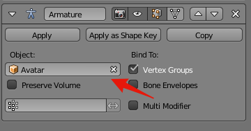
To accomplish either of the following two methods, the mesh needs to be parented to the armature. This can either be done by choosing ‘With Empty Groups’ from the Armature Deform menu (which we got to by selecting the mesh, then the armature – both in object mode – then hitting hotkeys Control + P) OR selecting the mesh and adding an Armature modifier, taking care to point the ‘Object’ field in that modifier to the appropriate armature.

Once this is done, the mesh can be weighted using the first, second or both of the following methods:
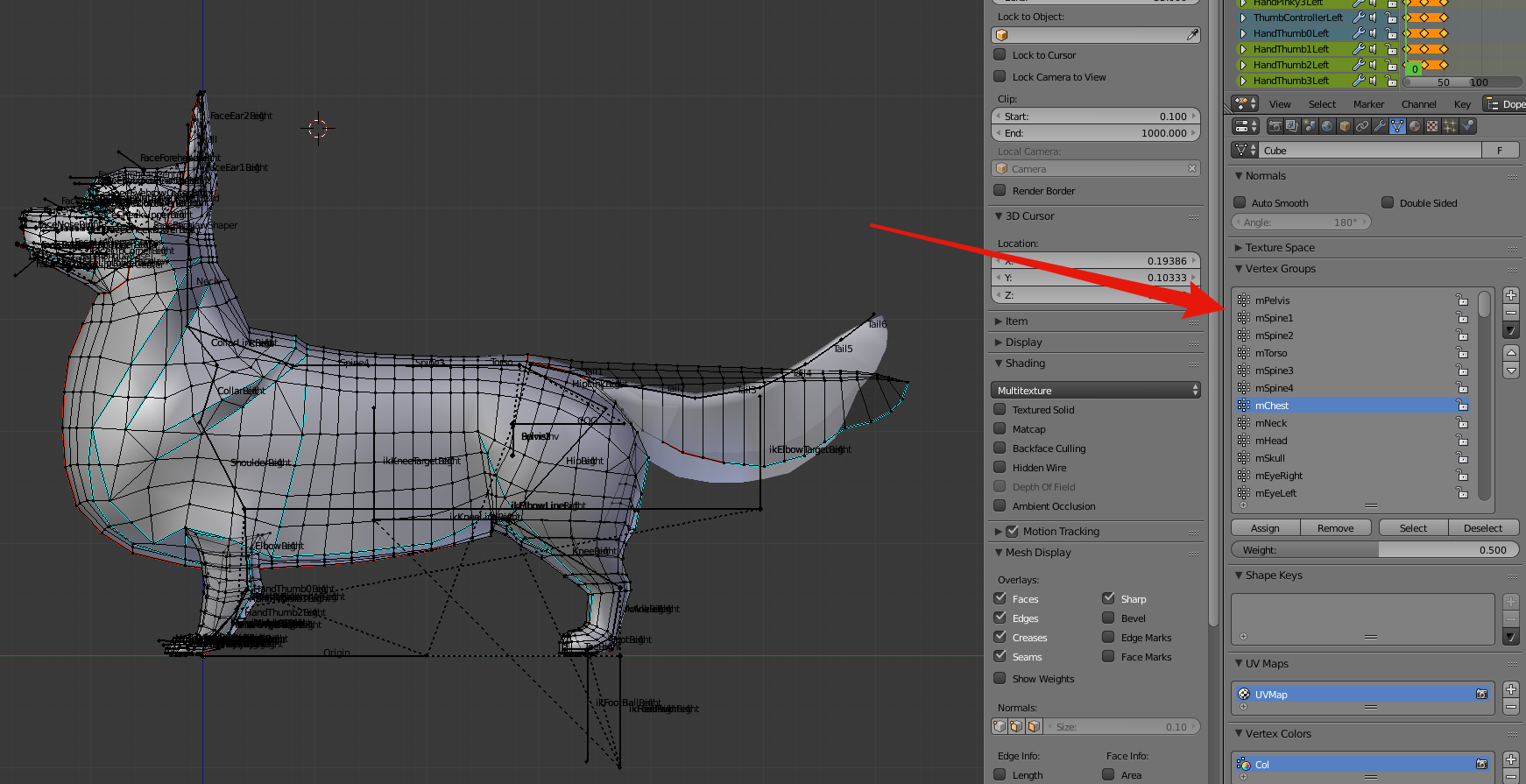
A) Assignment as an Edit Mode property – by selecting a single vertex or a whole group of them in Edit mode, you can affect their bone weighting by choosing the (above) indicated menu in the Edit properties tab, adjusting the associated weight and then hitting either ‘Apply’ or ‘Remove’. Vertices associated with a given bone can also be selected or deselected in this same menu.

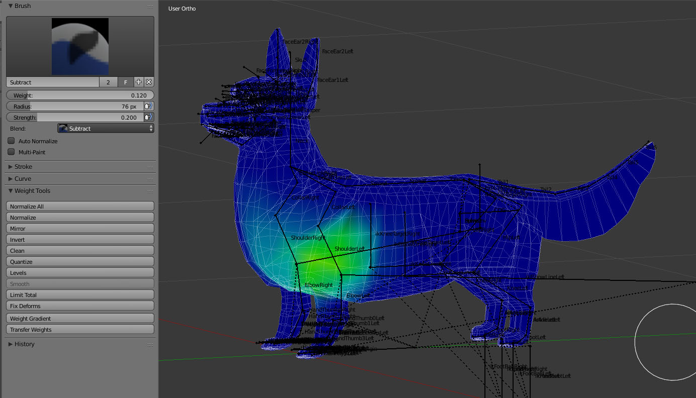
B) Weight Painting – This is a weighting method which allows you to visualize the degree to which verts are weighted to a particular bone through the use of colour. It allows you to use a digital brush to add, subtract, draw, lighten, darken, blur or otherwise affect bone influence, which in this mode is represented by a gradient of colour, ranging from blue (no influence) to yellow(middling influence) to red (full influence).

There are pros and cons to using each of these methods and almost 100% of the time, I use the second method *after* having used the first, in order to make it look more natural.

The weighting process with the cute, fuzzy and not-at-all skinny corgi has been, inevitably, a bit different (and long-winded) compared to weighting the sleek & non-squishy Drider avatar covered not too long ago.

I’ve always found this to be the case – coming to a happy medium between influence from multiple bones in a soft mass is a very organic process that depends heavily upon an understanding of what you want to move, and where.  Don’t be discouraged if this doesn’t work out right away. Understanding a lot of this comes with experience & experimentation.

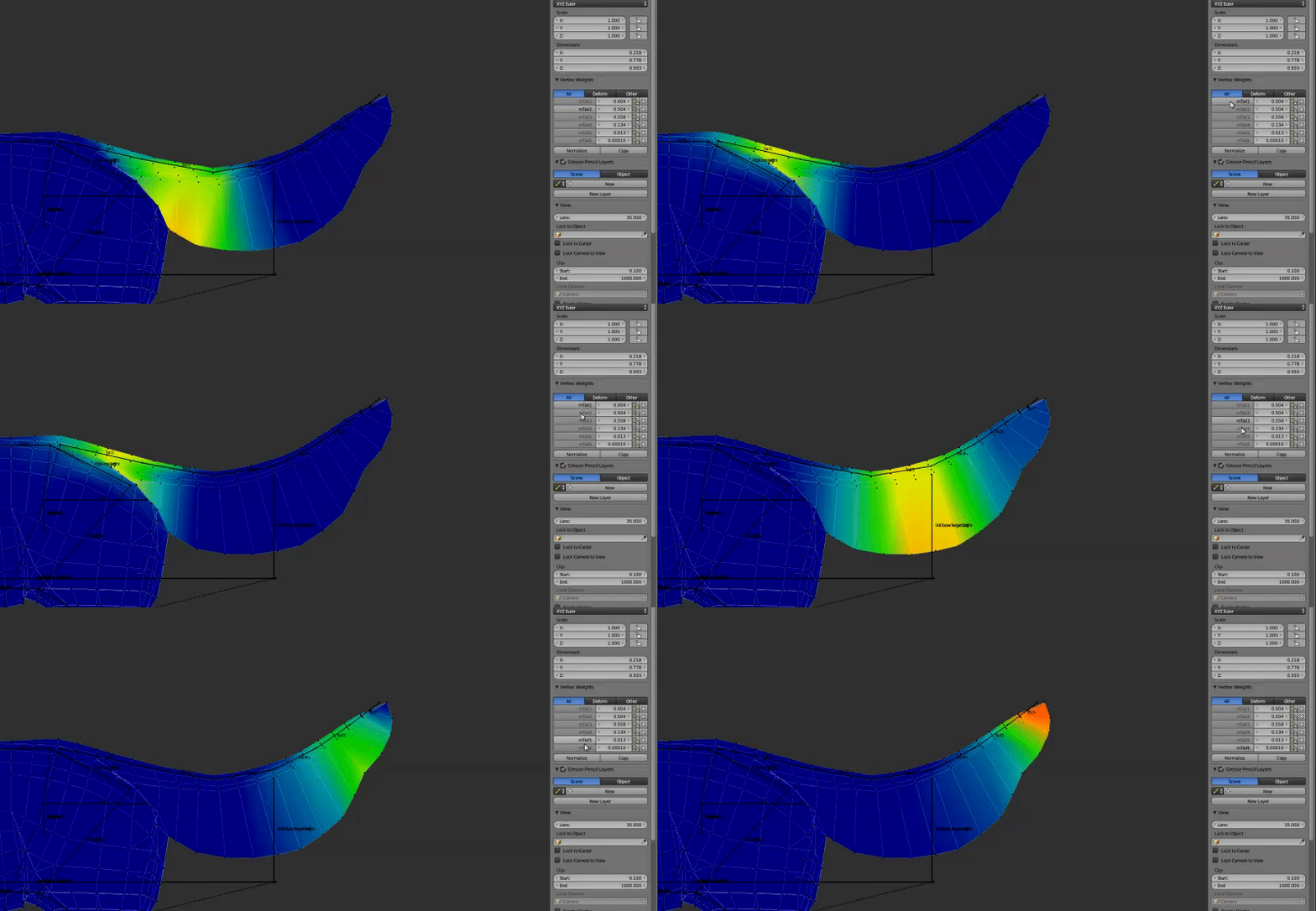
Whereas you can (for the most part) assign heavy influence of a rigid mass to a single bone, rigging to ensure smooth movement along a curvy mass often requires more of a gradiated transition – sometimes extending well past the immediate location of the bone.

For example, you could weight mesh along a tail rigidly, but when it comes time to move it, the mesh will be overly faceted and easily visible from afar as being unnatural.
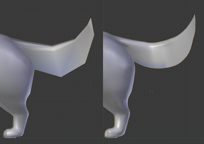
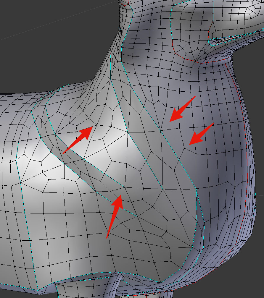
Adding geometry judiciously at this stage is a good way of adding a more natural look. This is also a great opportunity to smooth out weights along

It’s at this stage that I have added more geometry to critical areas, such as joints and the tail.

Maintaining a low poly-count to start with is very helpful in reducing additional work when it comes to correcting delicate bone weights, but it’s also in these cases where adding intervening geometry is appropriate, and this is why, despite having used a Subsurface division modifier to visualize, I have not applied such modifiers permanently to my mesh. Being able to easily select and divide up edge loops and rings manually allows me the greatest ability to create more natural shapes while maintaining clean edge-flow.

The weighting and animation processes are inevitably intertwined. In the next little while, I’ll not only be animating but correcting vertices with stray weights as well. I will often be animating, find that a certain movement affects the mesh in some negative way, and as a result find that I need to go back to editing weights to prevent any significant negative outcomes.

It’s also during this process that any final joint position tweaks should be made. As was mentioned in the previous post, it’s important to ensure any such position changes are carried out between *both* the Control bones (green) and the Deform bones (blue, purple, red). Failing to do so can cause some unpredictable results upon export.
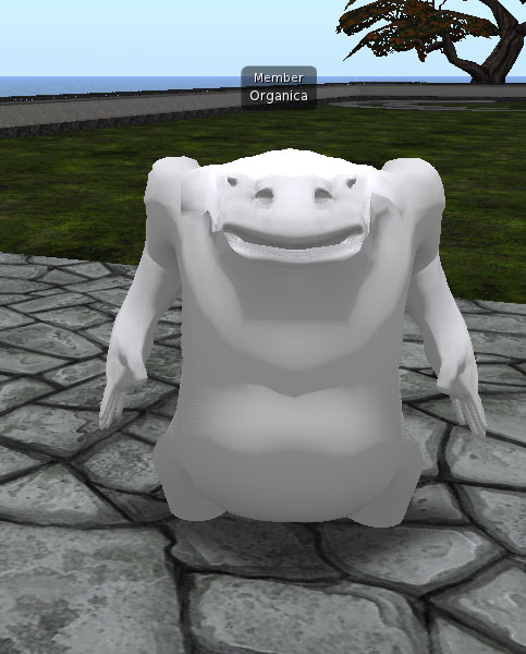
(which happened here some time ago while working on the Yeti)

So far, I’ve explained the concept of these weighting methods and discussed a few pitfalls, but I’d like to delve a little deeper next week with some video content, demonstrating the use of these Weighting tools in greater detail. If you’re looking to learn about weighting with Blender & Avastar and have any particular questions for me to work in to these videos, please leave a comment here or drop by my Discord server for a chat within the next couple of days! (Latest March 4, please!)


If you enjoy what I’m doing here or think someone else might also find it of use, please feel free to share this blog with them. If you’d like to keep up to date with posts, the RSS for this blog is here, I can also be found on Twitter and Plurk. The Discord server is here.

If you really like my stuff, perhaps consider donating to my Patreon? Your continued support helps to produce weekly content (written, modelled, animated or otherwise) and helps to keep original content creation in Second Life!

Thanks for your support!
Corgi Week 1: Working with modifiers in Blender to help visualize advanced geometry efficiently

This week I figured I’d get started on some Wilds of Organica-related items, since the last couple weeks have been pretty landscaping and decor-heavy.

Linden Lab have taken the past few weeks off, as far as Content Creation user group meetings – they will resume tomorrow (Feb 15, 2018) at 1PM SLT, on Animesh 1 region (on ADITI grid).

It’s hard to gauge how much longer the testing period will take. When we last met, it seemed like development was ongoing, but felt like we were moving a bit closer toward final performance and animesh limits testing. There has been some push in terms of increasing the triangle limit, however I’m still of the opinion that 50K is far more than enough.


With that said, I’ve begun development on a new WoO product this week that would likely see use as either an avatar, animesh, or both. We’ll see how development goes moving forward – I’m excited to see just how well it can be implemented, given the positive experience I’ve had popping in animations and some basic scripts for existing content thus far.

When I’ve chosen a real-world subject, typically I’ll look up some basic reference material to get the proportions down. In this case, it’s mostly been looking up corgis on Google Image search. It’s easy to get caught up researching cute critters and your search results are likely to be the same as mine, so suffice it to say that I use such references as a touchstone to develop an idea of what age and proportion I want my avatar to be.

My preference, from a stylistic point of view, is to avoid being photorealistic in my translation of a real dog to SL dog. I don’t really enjoy the uncanny-valley look that often comes from taking references completely from photograph to projected final texture, so usually these references become proportional and very general references later on when I paint my fur textures manually.

In this case, I was going for non-puppy, but still on the young side, just to get a nice balance between lovable huge ears and adorable elongated & lowered carriage. I’ve also elected to go the non-docked route, although a bobtail option might be in the cards at some point.

The early hours of my avatar making process usually start with something very simple – like a box with some very simple extruded faces, to block out limbs, head, etc. Once I feel i have the main proportions down, I will usually toss on a few modifiers to help me get a clear idea of what the final product will look like, even if i might not apply all of these modifiers by the end of the project.


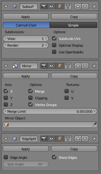
By using a SubSurf modifier, I can non-destructively visualize how my geometry might look if i were to subdivide and smooth. I don’t typically ever apply this modifier permanently because it’s too easy to just apply it and call it a day, without addressing some of the geometry problems that it introduces.

In particular, SubSurf tends to cause geometry to form vertices which either branch off in three or five directions, which is not ideal from an edge-flow perspective.  Also, it’s typically a lot more efficient to add edge loops and rings in areas where necessary, as opposed to allowing a modifier to add them all over your model.

I tend to add some edge loops and rings to some degree at this stage, to get the basic silhouette established, but do tend to add more later on, during the rigging stage, for added flexibility and attention to specific bone weights. One might conceivably use the ‘simple’ subdivision method rather than Catmull-Clark, however that subdivision method will not apply any vertex to vertex smoothing calculation and, at least for this use case, does little to add to this workflow.

I will typically mix the SubSurf modifier along with a Mirror and EdgeSplit modifier.

The Mirror modifier allows me to model on one side-only and have those changes propagate symmetrically.

I usually add an EdgeSplit modifier to help visualize the edge-flow of my model – in this case to help define key features in the surface as well as to give some definition to the fur.

I usually turn off angle calculations for this modifier, opting instead to define my sharp edges manually by right-clicking a sequence of edges, hitting Control E, then selecting ‘Mark Sharp’. Basically I want to adjust the geometry based on shapes I want to add to it, rather than adjusting the geometry based on what I have so far.

This helps to give the mesh a more distinct silhouette and to give me a better idea of how the geometry will need to be broken down later from the standpoint of someone who needs to rig and animate. As with the SubSurf modifier, unless I actually need a very sharp edge in my final model, I usually don’t permanently apply this modifier permanently either, since the resulting edge-splits will cause duplicate vertices that are not always necessary.

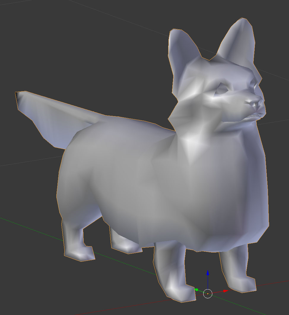
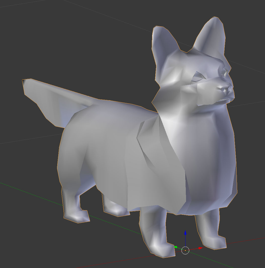
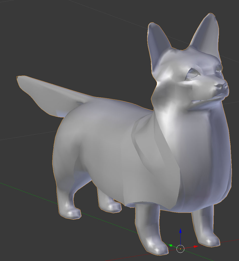
Below, you can see the difference between my Mirrored model (with no other modifiers added, but faces rendered as smooth), my mirrored model with edge-split, and finally with SubSurface divisions.

Once I am happy with this edgeflow and overall shape, I will usually begin modifying the Avastar Extended Bento skeleton to fit the avatar.

We’ll cover this, along with rigging our corgi, next week.


If you like what you see but don’t think it’s quite right for you, perhaps consider donating to my Patreon? Your continued support helps to produce weekly content (written, modelled, animated or otherwise) and helps to keep original content creation in Second Life!

Willow Tree Process (Part 2)

Today, I figured I’d touch on my process for creating textures.

While many folks prefer to use a photograph for their texture, I’ve always worked from scratch, creating my own textures digitally, while referencing a large number of photographs for ideas and clues about growth habit.

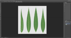
With respect to trees, I usually start with a few variations on a base leaf, taking care to work out the base silhouette.

In the case of weeping willows, the leaves are narrow,oblong, and taper gradually. While the final  product will ultimately be much smaller and not show small details like serrated edges, I usually add them anyway, along with veins so that these elements can give hints of themselves later.

It’s usually a good idea to create a variety of different leaves, even if they are a slight modification of one base shape. This allows the final branch texture to have some variation to it, even if, at a distance, the differences are small.

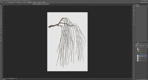
Sometimes, the use of traditional media for texturing is helpful too. I have used my share of drawing tablets but (even considering the use of Cintiq tablets) none of them can truly replicate the intuitiveness of simply taking pen or pencil to paper and simply drawing.  Sometimes, it’s just easier to sketch out a base to work from, clean it up or paint over it, rather than drawing and erasing ad nauseum via tablet, and this is what I’ve done here.

This and some other branches were drawn with pencil, scanned, cleaned up and painted over.  Using this process, I was able to put together a sideways branch, which is now at a prime stage for the addition of leaves in Blender.

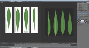
I usually start by unwrapping the UV of a plane to fill the whole area of a UV layout matching the proportions of my leaf texture. In the Node Editor, this object gets assigned a material with the leaf texture as a diffuse map. I additionally assign transparency to the material, using transparency from the texture to be the deciding factor in what gets rendered.

The plane gets cut up so that each piece of geometry gets a different leaf. I then also bring in the branch texture and put it on a vertical plane object (using a similar node setup as above) by adding it to my Diffuse Map node in the Node Editor.

Once this is in place, I divide the Blender windows such that I can view a preview in Render mode on one side as well as edit in either Texture or Wireframe mode on the other. This allows me to move leaf textures to match the branch texture relatively quickly, while still seeing the results (and how the transparent textures interact with each other) in real-time.

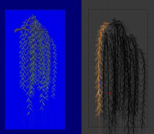
In this case, leaf geometry was laid out and duplicated with an Array modifier and also given a curve modifier, so that the geometry would conform to an extruded curve (to act as a stem). This allowed me to move and deform the long string of leaves in any way I wanted.

Special consideration is made to maintain variation and depth. Being able to use a 3D program to put together this texture means that I can take the time to create parts of the foliage which move forward or recede. Setting my texture workflow up this way also means it would be easy to replace the leaf texture later for other texture sets (fall colours, for example).

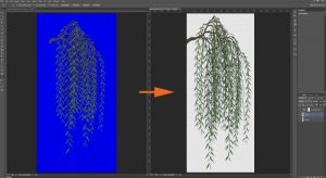
Once I have an arrangement I’m happy with, I add a solid emissive blue background, set up some appropriate lighting, position the camera and take a render (F12) of the camera view.

The result gets saved and opened in Photoshop. I select as much blue as possible, then delete it from the layer, leaving behind a transparent background. I then add a Hue/Saturation adjustment layer and de-saturate any remaining blue colour on the preceding layer.

Any additional cleanup should be done to the texture at this stage. I save a .PSD file as well as a .PNG at full size, then I repeat the placement process for branches along the full trunk. Once I have finalized placement, the file gets saved again as a .TGA, with an appropriate background & alpha channel and at a more SL-appropriate image size.

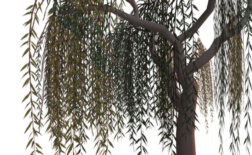
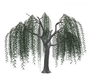
There can be a lot of experimentation at this stage and the solution, for trees, isn’t always a flat billboarded texture. As it stands, this tree still looks a little spare!

In my next article, I’ll show what additional geometry and texture work goes in to making the tree look believable from multiple angles.


If you found this or any other of my articles helpful, please consider becoming a Patron! Doing so supports further articles of this kind and my content creation in general.  Alternatively, if you like the sorts of things that I make for Second Life, drop by my Marketplace listing or my in-world stores and check out what I have to offer!

Unless otherwise noted, I (Aki Shichiroji) and this blog are not sponsored in any way. My thoughts are my own and not indicative of endorsement by any associated or discussed product/service/company.

Willow Tree Process (Part 1) & Bezier Curves

The last week has been a bit nuts!

Family is up from the States this week, so there was a family dinner. I also took a bit of free time earlier today to pick up a lovely vintage table for my kitchen, which is sorely lacking in the style department.

I am overseeing and creating content for a couple of new work projects and hope to be able to talk more about them soon – in the mean time, I figured I’d touch a bit on some work in progress I’ve got in mind for an upcoming Organica release.

It’s been a *long* while since Organica offered a weeping willow. Simply put, it’s mainly because I am not real big on flexi prims being linked in to mesh and, back when I did make some, we only had alpha blending (and not masking) – so it would be common to run in to issues where some textures would overlay others in an undesirable fashion.

With those caveats in mind, I figure it’s a good time to revisit willows, because let’s face it – a naturally moving  tree would be a great example of non-animal Animesh.

While I won’t touch on the rigging just yet here, I will at this point discuss my general modelling & UV layout process.

The process begins with a simple cylinder – usually with no more than 12 sides, and with the length divided a multitude of times. I usually create the UV layout for this cylinder pretty early on (even though I do later unwrap the geometry again) because multiple copies will be made of this cylinder and it’d be nice not to define seams for each and every one.

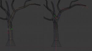
While I could probably define the shape of the geometry by moving the verts around,  lately I’ve taken to adding a Bezier Curve nearby and applying the curve as a modifier to the cylinder, taking care to apply scale and location before any heavy modification takes place.

By using a modifier, non-destructive changes can be made, allowing for a considerable amount of experimentation in placement and rotation prior to committing to a final shape. In this case, I am moving various nodes in the bezier curve to direct the overall direction of the mesh.

How does one use Bezier curves?

Assuming you are already familiar with how to move, rotate, scale and extrude vertices, edges and faces in geometry, Bezier curve nodes are similar to individual vertices (although more accurately, they are very similar to NURBS nodes).

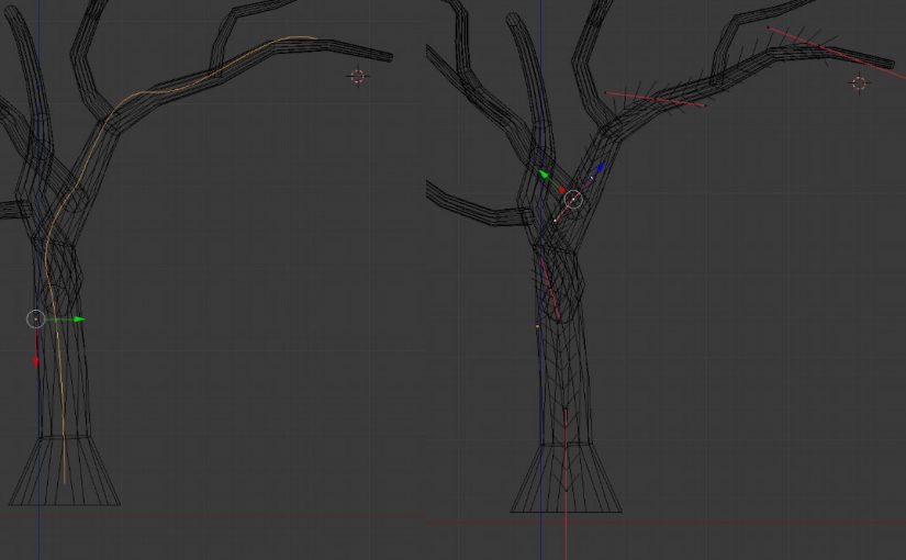
A Bezier Curve in Blender (in object mode on left, edit mode on right)

Basically, each node along a curve is accompanied by a pair of handles which control the direction of the curve directly before and after the node. They are always 180 degrees from each other. The closer these handles are to the node, the shorter the area of influence they will have.

The default bezier curve will give you two nodes. You can add nodes in between by dividing the space between the two in the same manner as you would between two vertices. You can also extrude additional nodes from the start or end of the curve.

You can either apply this curve to existing geometry (using the ‘Curve’ modifier’) or extrude some basic geometry along the curve (using the ‘Curve’ properties menu, when the curve is selected). There are some additional advanced things you can do to this extruded geometry (such as non-destructive tapering or bevelling) but for the purposes of this demo, I have only applied my curves to geometry as a modifier.

It should be noted at this point that, even at top level geometry, I do not subdivide at this point. This is important, since fixes will later be necessary to clean up the results of proceeding workflow. It’s way less hassle to redirect and merge fewer vertices than more. If smoother, more curvaceous transitions are needed, subdivisions should occur after the final UV layout has been finalized (IE: not now!)

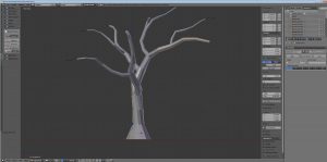
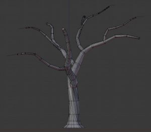
After the trunk has been defined, I select both the mesh and the curve and duplicate them at the same time, adjusting basic position, scaling and rotation at the Object level, then editing individual branches for variety by selecting the appropriate curve and editing in edit mode.

After I am satisfied with all the branch placement, I join each branch to the main trunk using a Boolean Modifier (‘union’ setting) to create the branch geometry in the same object as the trunk and also to join it with the trunk. This leaves behind a copy of the original branch, which can either be archived to a different layer or deleted entirely.

I do this for all of the branches, then go back and check each of the joints between the branches and trunk.

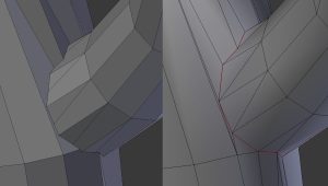
Before (left) and after (right) some vert cleanup at the branch/trunk joint. Also, seam assignment.

Typically, use of the boolean modifier will create extraneous verts, showing the point at which each face intersected with its adjacent geometry. This is, by and large, undesirable and I will usually either merge several extraneous verts to converge on one desired vert OR i’ll select edge loops and slide them in the correct direction, taking care later to remove any remaining duplicate vertices. Checking for N-gons (polygons with more than 4 edges) should also be done at this stage.

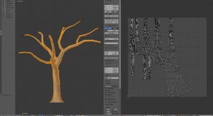
Cleanup is done around each joint, after which I attempt another UV unwrap to achieve a nice layout that is fairly clean, not overly stretchy, correctly scaled and laid out in a convenient direction.

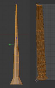
Tree trunk & branch UV layout

The overall silhouette and UV layout have been achieved. Further modifications  within these constraints (additional edge loops to create more curves, for example) would be ideal at this point.

We’ll leave it here for now. Next week, I’ll discuss foliage geometry, layout and general texture creation.


Did you know I have a Patreon account? If you enjoy this content, please consider becoming a Patron! It helps me create more like it and offers a variety of rewards. Alternatively, if you like the sorts of things that I make for Second Life, drop by my Marketplace listing or my in-world stores and check out what I have to offer!

Unless otherwise noted, I (Aki Shichiroji) and this blog are not sponsored in any way. My thoughts are my own and not indicative of endorsement by any associated or discussed product/service/company.

It’s spring! :D

And with spring comes new growth!

Maples #2 & 3 have been updated with spring foliage! They’re now being bundled with all mod/copy/no transfer editions of these trees. If you already own the autumn foliage editions, send me an IM or notecard explaining such and I’ll drop a copy of these spring editions on you for free!

Ficus Benjamina is also now available! Inspired by banyan-type fig trees from Asia, this tree is just under 20m in height, consisting of 61 prims and was made from scratch in Blender & Photoshop.

That said…

Far be it from me to poo poo people from using Blender and not actually provide help.

Many many people complain about Blender’s interface being too complicated etc etc. As a noob, i felt that too, yet ended up pushing through the initial learning curve and ended up finding Blender is actually really flexible. I’m still a noob! But I do find Blender very comfortable to work with and find it provides the most options towards creating things that I want.

Towards that end, I did a bit of searching for tutorial videos today and here is what I found:

Introducing the Blender 3D Environment by Glen Moyes is a clear and concise example of how you can make the Blender interface work for you (and not the other way around). In particular, the Blender Interface video is most useful to those who are starting out with the interface and are confused at how to make it work.

Lex Zhaoying’s tutorial teaches how to make a simple martini glass using a NURBs sphere and how to convert it to a sculptie texture you can then import in to SL. This is the tutorial that I held as a touchstone when I was first starting out because the process towards generating a sculptie texture was initially long and confusing. Nevertheless, it was necessary to understand the *how* of making them in order to properly edit them later.

Domino Marama’s Blender Scripts are explained here(SL Building Tips forum – requires verified payment info) and include utilities that allow the import of sculptie maps in to Blender for editing, as well as a utility that makes the mesh to UV texture process go MUCH faster.

The Second Life Building Tips Forum is also extremely useful to be a part of, but can only be accessed if you have verified your Av’s payment info. If your account is verified, make sure you’re logged in to get in on this wealth of information. There are a lot of tips and tricks provided that have helped me more than a few times when i’ve gotten in to ruts.

Additionally, as far as general process tips with Blender:

1) I always start with a NURBs object, whether sphere, torus (Blender calls them donuts), plane or cylinder. These are the four fundamental shapes SL will recognize. Starting out with these shapes when making sculpties will save you the headache of having to recreate them later in the long run.

2) Subdivide these shapes in order to add additional control points, but DO NOT add or extrude points from these shapes. SL requires a square texture to create your sculptie, and adding/extruding points outside of your object will prevent this! If you must add additional shapes outside of your first object, simply create another object and export that as a sculptie as well.

3) Many people stress the need for sculpties to be modelled in NURBs mode. This is not necessarily true. Modelling exclusively with NURBs is recommended because NURBs is the method SL uses to create its sculpties… BUT it needs to use a UV map that was created from a mesh anyway. NURBs can be rather clumsy to work with if you’re not familiar with them, and due to the manner in which they control an object’s mesh, it’s easier to make smooth, basic objects with them. IF however, you require greater detail, converting the object to a Mesh and manipulating points and vertices may provide you with greater flexibility. Personally, I start out with NURBs, block out the major shapes that I want, then convert to mesh and edit vertices individually until I get what I want. I then map the object to a UV Map using Domino’s ‘Render – Bake Second Life Sculpties’ tool to get Blender to generate a sculptie.

That’s what i can think of at the moment. At some point I’d like to make a short video describing this process that might help. That’s going to be dependent on what software I can find that will help me do this.